Physical Computing - Nervous Servo
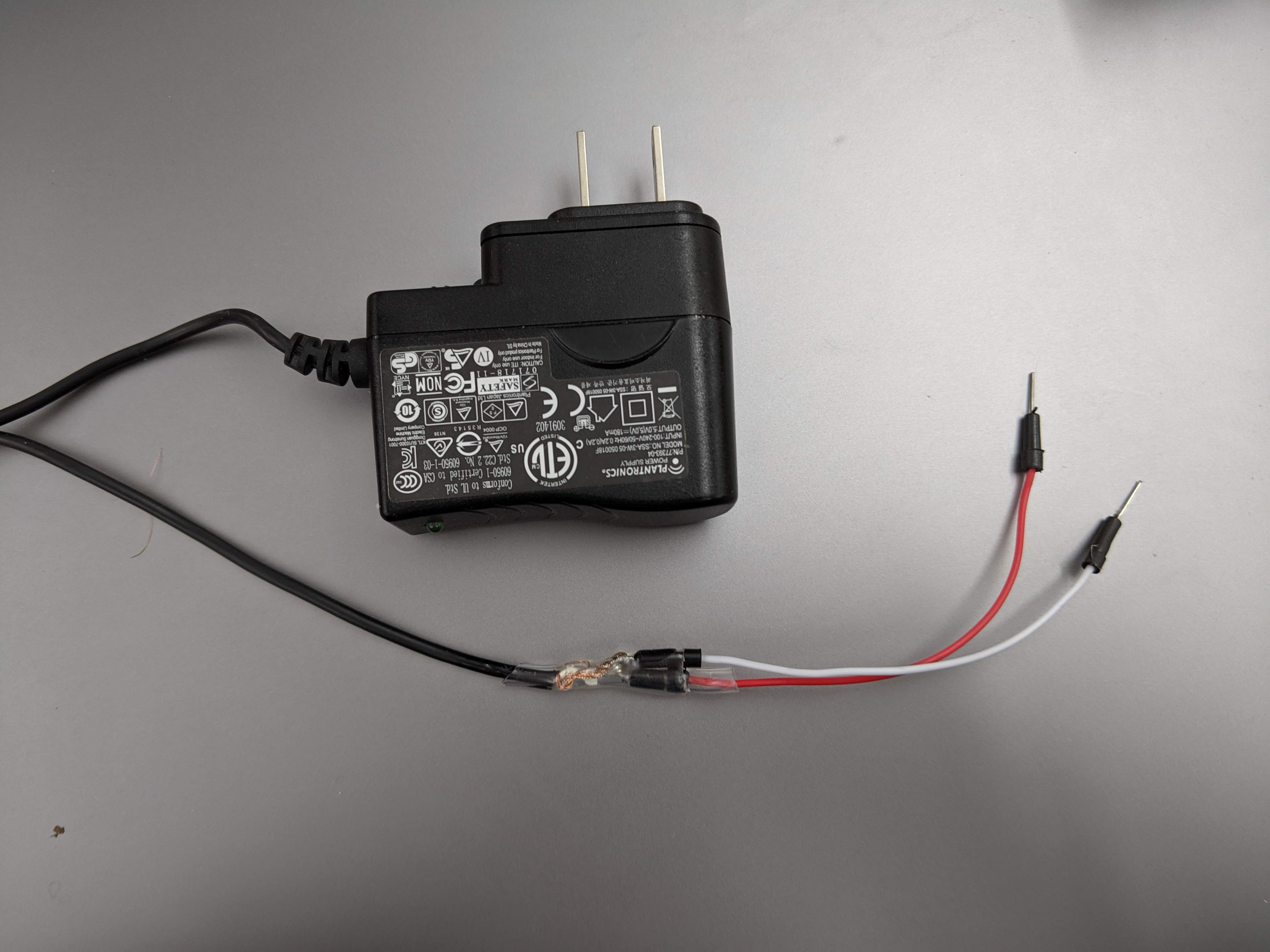
Preparing the Power Supply
The servo motor runs best on 5V DC - since the Arduino Nano only supplies 3.3V out, we’ll need a separate way of powering the motor. I found a 120VAC to 5V DC phone charger in the junk pile and figured that it would be a useful exercise to convert this into a usable power source. I snipped off the USB end revealing a copper stranded wire sheath and a copper stranded core with its own insulation sleeve. After stripping the internal sleeve, A quick multimeter test confirmed that the outside sheath was the ground connection and the inside core was the +5V DC connection. I soldered a pair of color-coordinated jumper leads to the pair of copper strands and sealed the connections with heatshrink.
Controlling the servo with a photoresistor
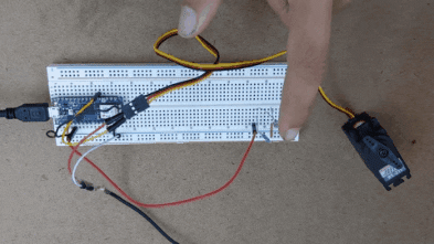
I wired a photoresistor into the A0 pin, with a parallel resistor allowing a connection to ground. At first I had the resistor in series with the photoresistor, but this gave me some trouble reading meangingful values from the photoresistor. My current thought is that the voltage read by the A0 pin never actually changes if the second resistor is in series. With the second resistor in parallel, the balance of voltage shifts as the resistance of the variable resistor changes which ultimately translates to usable data for the Arduino.
After fixing this mistake we can control the position of the servo by adjusting the amount of light the photoresistor is exposed to! It’s not a very fine level of control, but it works nonetheless.
Nervous Servo
I thought it might be fun to introduce some self-reference into this system. The photoresistor responds to light, and the servo’s rotation has the potential to effect change in the physical space. Is it possible to create a sort of feedback loop, out of which some more interesting behavior might emerge?
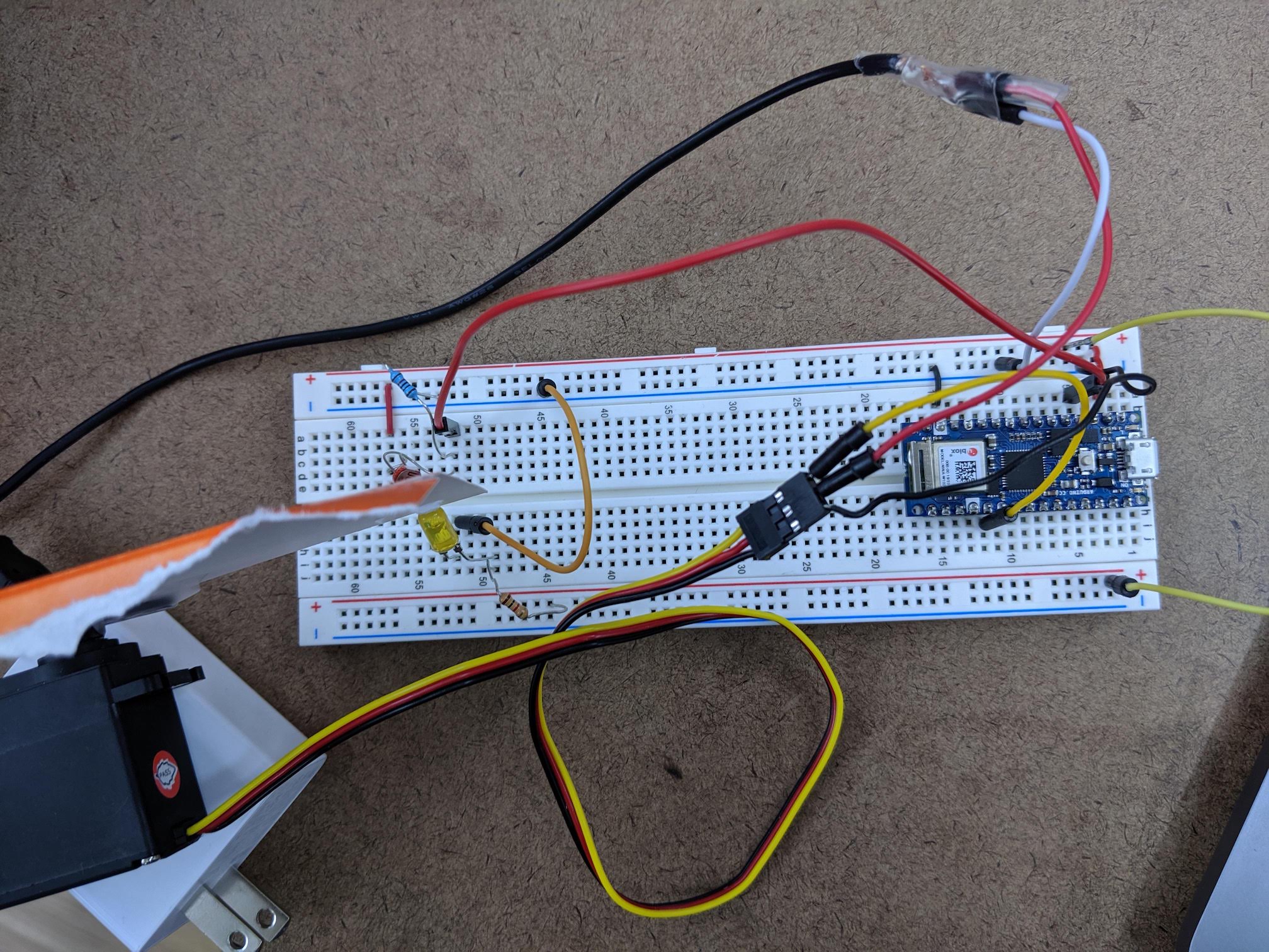
Paper affixed to the servo with scotch tape and careful positioning allows the rotation of the servo to shade the photoresistor. To accentuate the difference in light, I wired an LED in right next to the photoresistor. When the servo arm is set to about 40 degrees, the paper blocks the photoresistor from sensing the light from the LED. When the servo arm is set to about 80 degrees, the paper is lifted. So, with careful mapping of light sensing values, we can make the servo arm lift up when it can’t see the LED and go down when it can, causing an endless loop of movement.
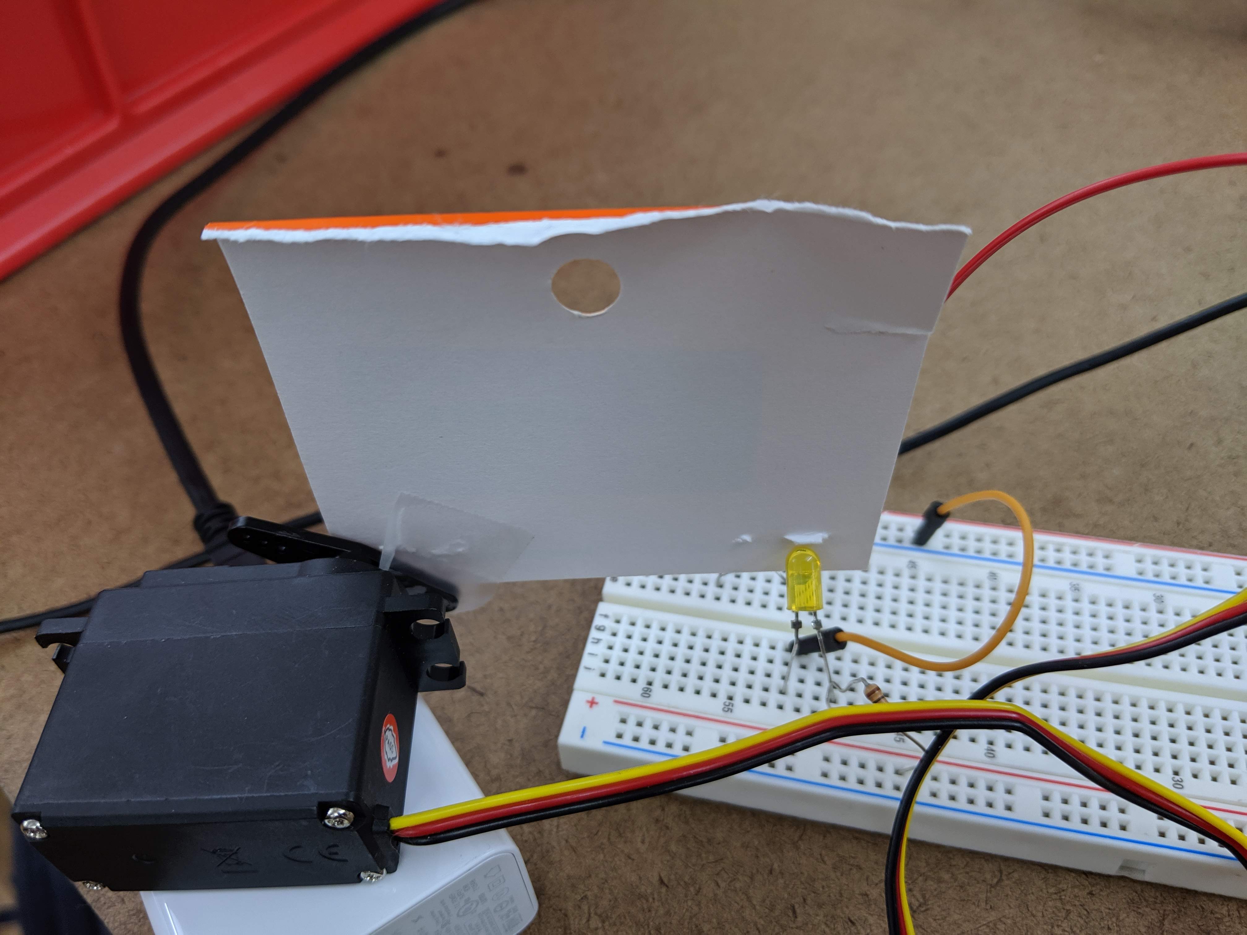
The fun part is that since the photoresistor responds to all environmental light and not just the light from the LED, movement and gestures of an observer have the potential to affect the pace of the servo’s motion, and in some cases can stop it entirely.
#include <Servo.h>

Servo servo;
int servoPin = 2;

void setup() {
  servo.attach(servoPin);
  Serial.begin(9600);

}

int T = 4500;
void loop() {
  int lightSensor = analogRead(A0);

  // Map the light sensor value to a velocity of the servo arm
  // so that the movement is a bit smoother and less jerky
  int dT = map(lightSensor, 350, 400, 10, -10);
  T = T + dT;
  Serial.print(lightSensor);
  Serial.print(" ");
  Serial.print(dT);
  Serial.print(" ");
  Serial.print(T);
  Serial.print("\n");
  if (T < 4500) {
    T  = 4500;
  }
  if (T > 8000) {
    T  = 8000;
  }
  servo.write(T/100);

}